
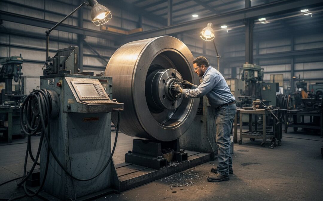
How much of your maintenance budget vanished into vibration-induced fatigue last year? Industry studies indicate that 40% of unscheduled downtime in heavy industrial plants stems from uncorrected rotor unbalance. You’ve likely seen the results: a critical pump starts humming, the seals fail prematurely, and you’re pulling a unit three months before its scheduled overhaul. It’s a cycle that guts your productivity. Implementing precision dynamic balancing for rotating equipment isn’t just about stopping the shake; it’s about shifting your facility from reactive repairs to a state of predictive reliability.
We understand that interpreting complex balance reports can be a headache when you’re under pressure to get back online. This guide provides an expert breakdown of the physics and ISO 21940-11 standards required to extend your Mean Time Between Failures. You’ll learn how adhering to G1.0 or G2.5 balance grades can lower energy consumption by as much as 12% through reduced friction. We’ll walk through the technical steps to ensure your assets meet documented compliance and finally achieve the long-term reliability your operations demand.
Key Takeaways
- Discover how the physics of centrifugal force converts minor mass offsets into destructive loads that compromise your equipment’s structural integrity.
- Differentiate between single-plane static corrections and the complex two-plane dynamic balancing required to eliminate couple imbalance in high-speed rotors.
- Evaluate the strategic trade-offs between on-site field balancing and the high-precision environment of a dedicated machine shop for critical asset restoration.
- Learn to apply ISO 21940 balance quality grades, from G6.3 to G1.0, to ensure your machinery meets rigorous global performance standards.
- Understand why precision dynamic balancing for rotating equipment serves as the definitive final step in a successful maintenance strategy to minimize vibration and extend asset life.
The Mechanics of Imbalance: Why Precision Balancing is Non-Negotiable
Precision dynamic balancing for rotating equipment is the technical process of aligning a rotor’s mass centerline with its geometric axis of rotation. When these two axes don’t coincide, the rotor exists in a state of unbalance. This isn’t just a minor mechanical annoyance; it’s a fundamental physics problem that dictates the operational lifespan of your machinery. In a field environment, we see this most clearly when a rotor that feels stable at low speeds starts to vibrate violently as it reaches its design velocity.
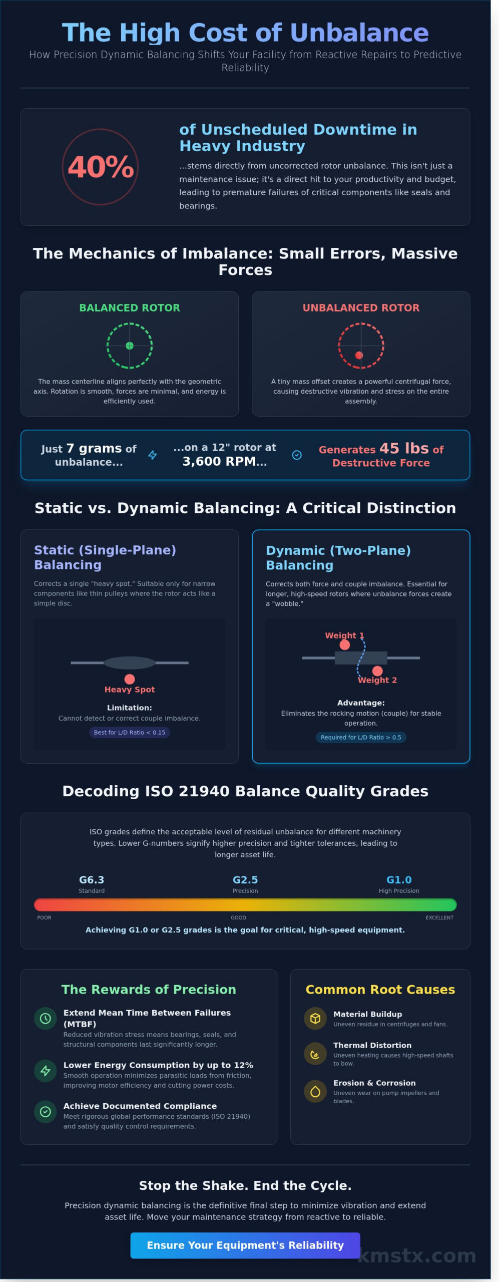
The physics behind this behavior is governed by centrifugal force. At high operating speeds, even a tiny amount of mass offset generates massive loads. For instance, just 7 grams of unbalance on a 12 inch diameter rotor spinning at 3,600 RPM translates into roughly 45 pounds of centrifugal force acting on the bearings. This force doesn’t stay constant. It’s a rotating vector that hammers the bearing races and housing every single revolution, leading to rapid component degradation.
To better understand the practical application of these principles, watch this video showing a high-precision balancing machine in action:
This constant hammering initiates the vibration-fatigue cycle. High vibration levels accelerate bearing race wear and compromise mechanical seal integrity. A 2018 industry report noted that vibration-related failures account for nearly 40% of unscheduled downtime in heavy industrial plants. Beyond mechanical failure, there’s a direct economic hit. Precision balancing reduces energy consumption by minimizing the parasitic loads caused by internal friction. Research indicates that correcting severe unbalance can improve motor efficiency by 2% to 5% depending on the equipment type.
Understanding the Root Causes of Rotor Imbalance
- Material Buildup: In industrial centrifuges, uneven cake distribution or residue buildup creates significant mass eccentricities.
- Thermal Distortion: High-speed turbines face thermal bowing, where uneven heating causes the shaft to distort slightly during startup.
- Erosion and Corrosion: In corrosive fluid pumps, impeller wear strips material away unevenly, shifting the mass center over time.
The Hidden Costs of ‘Good Enough’ Balancing
Accepting “good enough” balancing leads to cumulative damage that isn’t always obvious. Vibration travels through the machine, damaging structural foundations and support housings over years of operation. These secondary failures often manifest as loosened electrical connections or erratic readings from sensitive instrumentation. We define unbalance as a displacement of the principal inertia axis from the shaft axis. If you ignore this displacement, you’re essentially paying for the eventual destruction of your own hardware through avoidable mechanical stress.
Static vs. Dynamic Balancing: Understanding Force Vectors in Rotating Assets
Static balancing is the most basic form of correction, often referred to as “single-plane” balancing. It addresses the heavy spot on a rotor that’s naturally pulled to the bottom by gravity when the component is placed on knife edges or rollers. For narrow components where the width-to-diameter ratio is less than 0.15, such as thin pulleys or single-stage pump impellers, static correction is often sufficient. You’re simply neutralizing a single force vector that acts through the center of gravity. However, relying on this method for complex, high-speed machinery is a gamble that rarely pays off in heavy industry.
Single-Plane vs. Multi-Plane Correction
As a rotor’s length increases relative to its diameter, static balancing loses its effectiveness. When the length-to-diameter ratio exceeds 0.5, you’ve got to move to multi-plane correction. Static balancing can’t detect “couple imbalance,” which occurs when two equal weights are positioned 180 degrees apart at opposite ends of the rotor. While the rotor seems balanced when stationary, spinning it at 3,600 RPM creates a violent rocking motion as those weights try to pull the shaft in opposite directions. This is where precision dynamic balancing for rotating equipment becomes critical. We use vector math to resolve both the force and the couple components simultaneously. Dynamic balancing requires at least two correction planes to resolve the rotational moments.
The Role of Hard-Bearing Balancing Technology
Modern shops rely on hard-bearing balancing machines to handle the heavy lifting of data acquisition. Unlike older soft-bearing models that measure displacement, hard-bearing systems utilize high-sensitivity piezoelectric sensors to measure the centrifugal force exerted on the pedestals. These machines feature permanent calibration, meaning they don’t need a new trial weight setup for every different rotor weight class. The integrated software calculates the exact angular position and mass for weight addition or removal, often with sub-gram accuracy.
For a high-speed blower or centrifuge, even a 2-gram residual imbalance can lead to a 15% reduction in bearing life over a 12-month period. Implementing precision balancing standards helps mitigate these hidden mechanical stresses before the asset ever leaves the shop floor. Static balancing alone won’t cut it for industrial centrifuges or multi-stage turbines because it ignores the cross-effect of forces between different planes of rotation. Without two-plane correction, the centrifugal forces generated at operating speeds will inevitably lead to seal failure and unplanned downtime.
Field vs. Shop Balancing: Strategic Decision-Making for Heavy Industry
Choosing between field and shop balancing isn’t just a matter of convenience; it’s a technical decision that impacts the long-term MTBF (Mean Time Between Failures) of your assets. Precision dynamic balancing for rotating equipment requires an understanding of whether the vibration stems from a single component or the entire structural assembly. Field balancing, or “in-situ” balancing, addresses the rotor while it’s installed in its permanent bearings and foundation. This method accounts for the influence of couplings, pulleys, and the supporting structure, which often reveal “system” resonances that a shop environment won’t replicate.
However, field balancing has its limits. It’s often a reactive measure. When a 500 HP motor starts vibrating at 0.45 inches per second (ips) on a Friday afternoon, you don’t always have the luxury of a week-long teardown. In these high-stakes moments, integrating balancing with emergency machine repair Gulf Coast services allows plants to return to 90% capacity quickly. While field corrections can reduce vibration levels by 70% to 80% in a single shift, they can’t address underlying issues like journal wear or internal component looseness.
When to Choose In-Situ Field Balancing
In-situ balancing is the preferred route when the rotor is too large for economical transport or when the vibration is caused by the interaction of the entire drivetrain. It’s particularly effective for large fans, cooling tower assemblies, and wide-center-hung rotors. You’re balancing the assembly in its “as-run” condition, which is vital for systems where the foundation stiffness plays a role in the vibration signature. If the goal is a quick return to service to prevent a total plant outage, field balancing is the tool of choice. Just remember that it’s a surface-level fix; if the rotor has eccentric journals, no amount of trim weights will solve the root mechanical failure.
The Superiority of Shop-Based Precision
For a true restoration to OEM standards, the rotor must be pulled. Shop balancing occurs in a controlled environment using a hard-bearing or soft-bearing balancing machine. This setup allows technicians to achieve ISO G1.0 or G2.5 balance grades, which are nearly impossible to hit in the field due to ambient floor vibration and windage. Shop-based rotating equipment maintenance provides the opportunity for a full 360-degree inspection. Technicians can check for shaft runout, perform NDT (Non-Destructive Testing) on impellers, and verify bearing fit tolerances that are hidden during field operations. This level of precision dynamic balancing for rotating equipment ensures that when the part returns to the field, the rotor itself is a “known good” variable.
The Critical Speed Factor
The most complex challenge involves flexible rotors that operate near or above their first critical speed. These rotors change shape as they accelerate, meaning a balance weight that works at 900 RPM might actually increase vibration at 3,600 RPM. High-speed shop balancing is required for these assets to ensure stability across the entire operational ramp-up. If you’re dealing with multi-stage pumps or high-speed turbines, balancing at low speed is a recipe for a catastrophic wreck once the machine hits its first resonance peak.
ISO 21940 and Industry Standards: Decoding Balance Quality Grades
ISO 21940-11 stands as the definitive global benchmark for rotor balance tolerances. It provides a mathematical framework to determine how much residual unbalance a machine can tolerate before vibration levels compromise its service life. When we perform precision dynamic balancing for rotating equipment, we’re aiming for a specific “G” grade. This grade represents the maximum permissible vibration velocity in millimeters per second (mm/s) at the service speed. It’s a critical metric that separates a standard repair from a high-reliability overhaul.
Calculating the permissible residual unbalance isn’t a matter of intuition. It requires a precise formula: Uper = 9549 × (G × m / n). In this equation, G is the quality grade, m is the rotor mass in kilograms, and n is the service speed in RPM. If you’re running a 500 kg rotor at 3,600 RPM, the difference between a G6.3 and a G2.5 specification is significant. A G6.3 rating allows for roughly 875 gram-millimeters of unbalance, while G2.5 tightens that limit to about 347 gram-millimeters. Missing these targets often leads to bearing fatigue and premature seal failure within the first 12 months of operation.
Selecting the Right G-Grade for Your Asset
- G6.3: This is the standard for the majority of industrial hardware, including centrifugal pumps, general-purpose fans, and gearboxes. It’s the “workhorse” grade that balances cost-effectiveness with operational stability.
- G2.5: This tighter tolerance is mandatory for high-speed gas turbines and industrial centrifuge repair Texas projects. The high rotational velocities in these machines mean even minor unbalance creates massive centrifugal forces.
- The Risk of Over-Specifying: You might think requesting G0.4 for everything is a safe bet, but it’s usually a waste of money. Achieving G0.4 often requires laboratory-grade environments and specialized tooling that doesn’t provide any measurable benefit for a standard industrial blower or pump.
Interpreting Your Balance Certification
A final balance report is a technical affidavit of your machine’s health. You should always look for the “Initial Unbalance” versus the “Final Residual Unbalance” metrics. This delta shows exactly how much correction was needed. The report must clearly state the phase angles where weights were added or material was removed. Without the specific RPM used during the test, the data can’t be verified. Always check that the document includes a “Tolerance Met” confirmation tied directly to the ISO 21940-11 standard. This documentation is your primary defense against warranty disputes and a key part of your reliability history.
Don’t leave your machinery’s lifespan to chance. Consult with our technical experts to ensure your precision dynamic balancing for rotating equipment meets the highest ISO standards.
Integrating Precision Balancing into a Comprehensive Maintenance Strategy
Every major mechanical overhaul or industrial gearbox repair Houston operators commission should culminate in a final balance test. You can’t consider an asset fully restored if it hasn’t been verified under operational load conditions. Vibration analysis serves as the primary diagnostic lens in this process. It allows technicians to isolate 1x RPM frequencies that indicate mass imbalance from the high-frequency chatter of failing bearings or gear mesh issues. Without this empirical data, a repair is merely a series of parts replacements rather than a technical restoration.
KMS Technologies brings four decades of field and shop experience to every project. We don’t just spin a rotor and add weights until the lights turn green. Our team utilizes proprietary data sets gathered from thousands of successful interventions to ensure every asset meets or exceeds ISO 21940-11 standards. This scientific approach to precision dynamic balancing for rotating equipment transforms a standard repair into a long-term reliability solution. It’s the difference between a machine that simply runs and one that operates at peak efficiency for years.
The Balancing-Machining Synergy
You can’t balance a shaft that’s bent or journals that are out of round. Effective balancing often requires a trip to the lathe before the balancing stand. Our facility integrates precision machining with dynamic balancing to address these foundational mechanical issues. We’ve documented cases where correcting a 0.005-inch runout eliminated 80% of the vibration before the rotor even reached the balancing stage. A one-stop-shop approach ensures that the teardown, repair, and final calibration happen under one roof. This maintains a strict chain of custody and ensures that custom-fabricated components restore the original mass distribution of the OEM design.
Establishing a Proactive Balancing Schedule
Waiting for a catastrophic failure is a recipe for expensive, unplanned downtime. We recommend using routine vibration monitoring to trend imbalance growth over months or years. For high-criticality assets, scheduling a “check-up” balance during a planned 24-month outage can extend bearing life by 50% or more. It’s about moving the needle from reactive maintenance to true asset management. By identifying subtle shifts in balance early, you avoid the secondary damage that vibration causes to seals, couplings, and housings.
If you’re seeing increased vibration levels or suspect your machinery is running rough, contact KMS for a technical evaluation of your rotating equipment. Our experts provide the technical depth needed to solve complex vibration challenges in the most demanding industrial environments.
Securing Long-Term Industrial Reliability
Achieving peak industrial reliability depends on the systematic elimination of parasitic vibration through precision dynamic balancing for rotating equipment. When your assets are balanced to strict ISO 21940 specifications, you aren’t just quieting the shop floor; you’re actively protecting bearings, seals, and couplings from premature fatigue. KMS Technologies leverages 40+ years of heavy industrial repair experience to solve complex vibration issues that standard maintenance routines often miss. We utilize Schenck hard-bearing balancing technology to provide the highest level of measurement accuracy currently available in the industry.
Every job we complete includes a detailed ISO-compliant balance certification, providing your team with documented proof that the equipment meets or exceeds required quality grades. Whether you’re managing a single critical fan or an entire fleet of turbines, these technical benchmarks ensure your machinery stays in the field longer. It’s about moving from reactive fixes to a strategy of engineering excellence. Request a Technical Consultation for Precision Dynamic Balancing at kmstx.com. We look forward to helping you stabilize your most critical rotating assets.
Frequently Asked Questions
What is the difference between static and dynamic balancing?
Static balancing handles the center of gravity on a single plane, while dynamic balancing corrects centrifugal forces across two or more planes while the rotor spins. You’ll see static issues when a part always stops with the heavy side down. Dynamic issues only show up at speed, where uneven mass distribution creates a couple imbalance that vibrates both ends of the machine.
How often should industrial rotating equipment be dynamically balanced?
Maintenance intervals depend on the machine class, but most critical fans and motors require a check every 8,000 run hours or during annual turnarounds. According to ISO 21940 standards, high-speed turbines might need more frequent monitoring. If you’ve replaced a component like an impeller or experienced a 15% increase in vibration velocity, it’s time for a re-balance.
Can you perform dynamic balancing on-site without removing the rotor?
Precision dynamic balancing for rotating equipment can be performed in-situ using portable vibration analyzers and laser tachometers without pulling the rotor. This process saves the 3 to 5 days typically lost to teardown and shipping. Technicians attach trial weights directly to the shaft or hub while the machine runs at operating temperature, ensuring the balance accounts for real-world thermal expansion.
What are the most common signs that a machine is out of balance?
High radial vibration at the 1x running frequency is the primary indicator that your rotor is out of balance. You’ll often see 70% or more of the vibration energy concentrated at this specific frequency on a spectrum analyzer. Other physical signs include premature bearing failure within 6 months of installation, loosened foundation bolts, and structural cracks near the bearing housings.
What is an ISO G2.5 balance grade and why does it matter?
The ISO G2.5 grade is a specific quality level where the residual unbalance results in a vibration velocity of 2.5 millimeters per second at operating speed. It’s the industry standard for high-performance pumps and electric motors. Achieving this tight tolerance reduces internal loads on bearings by up to 40%, which directly extends the mean time between failures for your critical assets.
How much does precision dynamic balancing typically cost?
Costs for dynamic balancing vary based on the rotor’s weight class, the number of correction planes, and whether the work happens in a shop or the field. Shop rates often include a base setup fee plus an hourly rate for the balancing technician. Field service typically adds travel expenses and a daily minimum. Every 500-pound fan and 5,000-pound turbine has different accessibility and safety requirements.
Will dynamic balancing fix a machine that has bad bearings?
Dynamic balancing won’t fix a bearing that’s already suffered surface fatigue, spalling, or cage damage. While balancing reduces the force hitting the bearing, it can’t restore lost metal or fix a 0.005-inch clearance issue. If your vibration data shows high-frequency floor noise or non-synchronous peaks, you’ve got to replace the bearings before the balancing weights will do any good.
What information do I need to provide for a dynamic balancing quote?
You need to provide the rotor weight, the maximum operating RPM, and the shaft diameter to get an accurate quote. Mention if the unit has accessible balance planes or if guards need to be removed for weight placement. Providing a recent vibration report with 1x amplitude readings helps the shop determine if precision dynamic balancing for rotating equipment is the right solution.