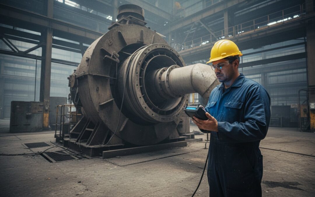
Most vibration issues attributed to unbalanced rotating equipment aren’t actually caused by mass distribution at all. You’ve likely stood on a production floor where a 1,200 RPM centrifugal pump is shaking the anchor bolts loose, assuming a quick field weight will stop the bleed. It’s a common frustration in heavy industry, especially when a $12,000 bearing replacement only provides a temporary fix before the vibration returns within 90 days. We’ve seen that nearly 40% of vibration cases labeled as unbalance are actually symptoms of underlying issues like structural resonance or soft foot.
This article provides a technical deep-dive into these common misconceptions to help you secure genuine operational stability in your high-speed assets. You’ll learn how to identify the true root causes of mechanical oscillation so you can stop chasing symptoms and start increasing your Mean Time Between Failures. We’ll also break down the specific criteria that dictate when a precision shop balance is required over a standard field fix to ensure your critical lines stay up for the long haul.
Key Takeaways
- Learn why excessive vibration doesn’t always signal a mechanical issue and how to distinguish between temporary field fixes and true rotor stability.
- Understand the specific physics of static, couple, and dynamic forces to see how increased RPM exponentially amplifies the impact of unbalanced rotating equipment.
- Discover the direct relationship between “tolerable” vibration levels and bearing life reduction to prevent premature metal fatigue in your shafts and couplings.
- Identify external factors like structural resonance and “soft foot” that often mimic unbalance symptoms, ensuring you address the actual root cause of vibration.
- Explore the forensic approach to multi-plane dynamic balancing required to restore precision and operational reliability to complex industrial rotors.
Debunking Common Myths About Unbalanced Rotating Equipment
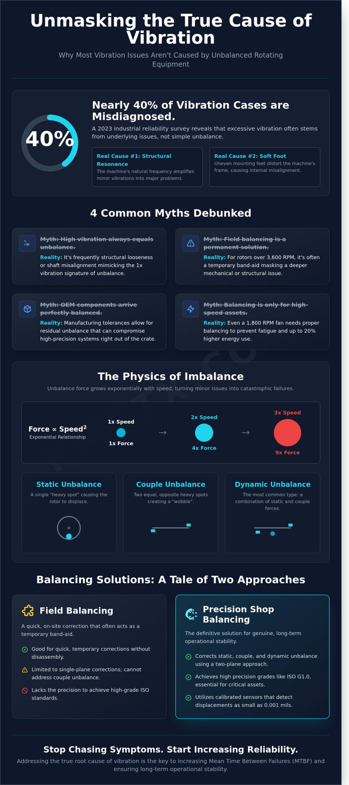
Assuming that every shake in a machine signifies a balance issue is a costly mistake. In reality, vibration analysis data from a 2023 industrial reliability survey shows that nearly 40% of excessive vibration cases stem from misalignment or resonance rather than unbalanced rotating equipment. Mechanics often jump to balancing because it’s a familiar fix; however, ignoring the root cause leads to premature bearing failure within 6 months of the supposed repair. You’ve got to look at the data before you start adding weights.
- Myth 1: High vibration always equals mechanical unbalance. It’s frequently structural looseness or shaft misalignment that mimics the 1x vibration signature.
- Myth 2: Field balancing is a permanent solution. For rotors exceeding 3,600 RPM, field weights are often just temporary dampening for a deeper mechanical issue.
- Myth 3: OEM components arrive perfect. Manufacturing tolerances allow for residual unbalance that can compromise high-precision systems right out of the crate.
- Myth 4: Balancing is only for high-speed assets. Even a standard 1,800 RPM industrial fan requires adherence to ISO 21940-11 standards to prevent housing fatigue and 20% higher energy consumption.
The New Component Fallacy
Don’t assume a component is ready for service just because it’s brand new. Standard machining tolerances often allow a residual unbalance of up to 5 grams per inch of radius on individual parts. When you stack a new impeller onto a new shaft, those individual variances can combine. This “assembly stacking” often results in a total system unbalance that exceeds G6.3 specifications by 25% or more. Precision shops must balance the rotor and bowl as a single unit to ensure operational stability. Balancing components individually and then bolting them together is a recipe for a 2:00 AM emergency shutdown.
Field Balancing vs. Precision Shop Balancing
Field balancing serves its purpose for quick corrections, but it’s often a technical band-aid. Single-plane field corrections can’t address the couple unbalance present in long-axis rotors, which requires a two-plane approach. Achieving an ISO G1.0 or G2.5 grade requires the controlled environment of a hard-bearing balancing machine. Without this precision, you’re likely masking a flaw that will resurface during a thermal cycle or a speed ramp-up. Unbalanced rotating equipment handled in the field lacks the calibration accuracy that a shop environment provides, where sensors can detect displacements as small as 0.001 mils.
The Mechanics of Imbalance: Static, Couple, and Dynamic Forces
Rotational unbalance occurs when the center of mass doesn’t align perfectly with the geometric axis of rotation. This mass eccentricity generates centrifugal force that grows exponentially with speed. If a technician doubles the operating speed of a motor, the force exerted by the unbalanced rotating equipment increases by a factor of four. This relationship explains why a minor weight discrepancy at 1,800 RPM becomes a catastrophic failure at 3,600 RPM. Managing unbalanced rotating equipment requires a deep understanding of how these forces interact across different planes of the rotor.
Static unbalance is the simplest form, often described as a single heavy spot on the rotor. In low-speed applications, like a 450 RPM industrial fan, gravity alone can identify this point. If the rotor is placed on frictionless rollers, it’ll always roll until the heavy spot reaches the six o’clock position. While static corrections are a baseline, they rarely solve vibration issues in high-speed industrial centrifuges or turbines where the rotor length exceeds its diameter.
Static vs. Couple Unbalance
Static unbalance involves a single force vector, but couple unbalance introduces a twisting moment. This happens when two equal masses are positioned 180 degrees apart at opposite ends of the rotor. You won’t find this on a static balancer because the weights cancel each other out at rest. When the machine reaches operating speed, these weights pull in opposite directions, creating a localized rocking motion. Field experts use phase angles to map this; a 180-degree phase shift between the inboard and outboard bearings is a telltale sign of a couple unbalance that single-plane corrections can’t fix.
The Reality of Dynamic Imbalance
In the field, pure static or pure couple unbalance is rare. Most technicians deal with dynamic unbalance, which is the vector sum of both forces acting simultaneously across multiple planes. According to ISO 1940-1 standards, dynamic unbalance is the condition in which the central principal axis of inertia is not coincident with the shaft axis. This misalignment creates non-uniform loading on bearing housings, often leading to premature seal failure or fatigue in the foundation. Utilizing advanced sensor integration allows teams to identify these complex force vectors before they cause a 15% drop in machine efficiency. This data-driven approach ensures that balance weights are placed with surgical precision, rather than through trial and error.
Why Tolerable Vibration Levels Lead to Catastrophic Failure
High-speed industrial assets don’t usually fail without warning. They degrade through precise physical mechanisms that often start with “tolerable” vibration. When unbalanced rotating equipment operates even slightly outside of its center of mass, it generates parasitic loads that fight against the machine’s design. This isn’t just a nuisance. It is a conversion of electrical energy into heat and structural stress. A motor consuming 500 kW might waste 1% to 3% of that energy just to overcome the internal friction and resistance caused by unbalance. Over a 12-month period, this translates to thousands of dollars in lost efficiency and unnecessary thermal load on the motor windings.
Impact on Bearing Longevity and L10 Life
Bearings are the first line of defense against rotor forces, but they are also the first to fail under unbalance. The relationship between load and bearing life is exponential, not linear. According to the Lundberg-Palmgren theory, a bearing’s L10 life is inversely proportional to the cube of the dynamic load. If unbalance forces increase the load on a bearing by 20%, its calculated service life is slashed by 42%. This increased pressure generates localized heat that degrades the viscosity of the lubricant. As the oil film thins, the risk of metal-to-metal contact rises, leading to subsurface fatigue and spalling. Effective rotating equipment maintenance requires addressing these dynamic loads at the source rather than simply increasing lubrication frequency.
Secondary Component Fatigue
Beyond the bearings, chronic vibration acts as a silent destroyer of structural integrity. A rotor spinning at 3,600 RPM subjects the shaft and couplings to 216,000 stress cycles every hour. This high-cycle fatigue can lead to crack propagation in the shaft radius or keyways, often resulting in a snapped shaft that destroys the entire housing. Vibration also travels through the drivetrain to affect other components:
- Fastener Loosening: Constant oscillation causes vibration-induced loosening (VIL) in foundation bolts and bearing caps, which further reduces the stiffness of the machine.
- Gearbox Misalignment: Unbalance disrupts the precision mesh of gear teeth, causing uneven wear patterns and pitting on the drive side.
- Seal Failure: Mechanical seals are designed for tight tolerances; even 0.002 inches of excessive shaft deflection can cause premature leakage and environmental hazards.
Replacing a failed bearing without correcting the unbalanced rotating equipment ensures the failure will repeat. In high-speed assets like centrifugal compressors, this cycle eventually leads to catastrophic metal-to-metal contact. When a rotor hits a stator at 10,000 RPM, the result is an immediate, high-energy release that endangers personnel and results in months of unplanned downtime.
Troubleshooting the Root Cause: When the Rotor Is Not the Problem
Vibration data often tells a deceptive story. When a technician identifies a high 1X peak on the frequency spectrum, the standard response is to assume the rotor needs weight correction. However, field data shows that approximately 35% of vibration issues initially diagnosed as unbalanced rotating equipment are actually caused by external mechanical influences. Identifying these false positives prevents the frustration of “balancing out” a symptom while the actual root cause remains unaddressed.
Structural issues like “soft foot” are frequent culprits in these scenarios. If a machine’s feet aren’t planar within 0.002 inches, tightening the hold-down bolts twists the frame and distorts the bearing housings. This physical stress creates a dynamic stiffness change that mimics the signature of unbalance. You can balance the rotor to a G1.0 specification on a shop bench, but as soon as it’s bolted to a warped base, the vibration levels will exceed acceptable limits again.
Resonance and Critical Speeds
Every industrial machine has a natural frequency. If the operating speed of your motor sits within 15% of this frequency, resonance occurs. This doesn’t mean the rotor is heavy on one side; it means the support structure is amplifying the tiny, inherent forces that exist in every rotating assembly. Differentiating between the two requires a coast-down test. If the vibration amplitude drops off sharply as the RPM decreases by just 100 or 200 units, you’re dealing with resonance. Operating near the first or second critical speed can increase vibration levels by a factor of 10, leading to catastrophic bearing failure in less than 500 operating hours.
Environmental and Process Factors
In high-speed applications, the environment changes the rotor’s physical geometry during the run. Thermal bowing is a common example. In shafts longer than 48 inches, a temperature gradient of 50 degrees across the diameter can cause the metal to warp. This creates a temporary unbalance that only exists at operating temperature and disappears once the machine cools down. If you’re seeing inconsistent readings, it’s often a sign that you need professional industrial centrifuge repair to address internal wear or thermal sensitivity rather than just adding weights.
Process-related factors that mimic unbalanced rotating equipment include:
- Material Accumulation: As little as 75 grams of dried process material in a 30-inch centrifuge bowl can throw the entire system out of tolerance.
- Uneven Erosion: In abrasive applications, conveyor flights or impellers wear unevenly, shifting the center of mass over time.
- Thermal Expansion: Machine components can expand 0.001 inches for every inch of length when internal temperatures exceed 250°F, changing the alignment and vibration profile.
If your vibration levels remain high after a precision balance, the problem isn’t the weight distribution. Contact our engineering team for a technical vibration analysis to identify the structural or process-related drivers behind your equipment’s instability.
Restoring Operational Stability Through Precision Dynamic Balancing
Solving chronic vibration requires looking past the digital readout on a handheld sensor. You have to deal with mechanical reality. A forensic approach starts by identifying whether the vibration stems from a simple mass imbalance or deeper structural issues like thermal growth or resonance. For complex industrial rotors, single-plane balancing is rarely enough. We utilize multi-plane balancing to account for couple unbalance, which occurs when the principal inertia axis intersects the shaft axis at the center of gravity but is tilted at an angle. This ensures stability across the entire length of the component.
Operational speed is another critical factor. Many shops balance at low speeds for safety, but centrifugal forces don’t always scale linearly. Balancing at or near the actual service speed reveals how the rotor behaves under real-world loads. We document every correction to ISO 21940-11 standards. This provides a clear, defensible record of balance quality that supports long-term asset reliability and helps avoid premature bearing failure.
The Precision Balancing Process
Every successful restoration begins with a rigorous mechanical inspection. We check for shaft run-out and housing eccentricity with tolerances often tighter than 0.001 inches. If the mass distribution is uneven, we rely on CNC machining for permanent correction. Removing material through precision milling is far superior to using temporary weld-on weights. Weights can detach during high-velocity operation or introduce localized heat stress into the metal. A machined fix ensures your unbalanced rotating equipment stays within spec for the remainder of its service life without the risk of “thrown” weights causing a secondary failure.
Ensuring Long-Term Asset Health
The job doesn’t end when the rotor stops spinning on the stand. Final verification involves comprehensive post-balance vibration reports and phase analysis to confirm the “heavy spot” is gone. This data becomes the foundation for your predictive maintenance schedule. By monitoring balance trends over 12 or 24-month intervals, you can catch issues like erosion or particulate buildup before they trigger a high-vibration alarm. If you’re dealing with critical machinery that can’t afford a day of downtime, our Precision Dynamic Balancing Services provide the technical expertise needed to stabilize your most demanding unbalanced rotating equipment. We focus on empirical results that keep your plant running smoothly and safely.
Protecting Your Assets Through Precision Engineering
Managing unbalanced rotating equipment requires more than just reacting to a high vibration alarm. It’s about understanding that even “tolerable” levels often mask underlying issues that lead to catastrophic failure. We’ve seen how ignoring these nuances results in unnecessary downtime. True operational stability comes from identifying whether you’re dealing with static, couple, or dynamic forces before they compromise your bearings. Relying on shop-floor guesswork isn’t a strategy; it’s a risk to your bottom line.
At KMS Technologies, we bring 40+ years of technical mechanical experience to every project. Our team utilizes in-house precision dynamic balancing performed to strict ISO standards to restore your machinery’s integrity. We understand that critical infrastructure doesn’t follow a 9-to-5 schedule, so we provide 24/7 emergency support to keep your operations moving. Don’t let minor oscillations turn into a major shutdown. You’ve worked hard to build your facility’s reputation; we’re here to help you protect it.
Request a Technical Consultation for Your Rotating Equipment
Frequently Asked Questions
What is the most common cause of unbalanced rotating equipment?
Material buildup on fan blades or impellers accounts for roughly 40% of all unbalance issues in industrial air handling systems. This uneven accumulation of particulate matter shifts the center of mass away from the geometric center of the shaft. Other frequent causes include manufacturing tolerances or thermal deformation that occurs during high-speed operation in 90% of heavy-duty rotors.
Can you balance a rotor without removing it from the machine?
Field balancing allows technicians to correct unbalanced rotating equipment while it’s fully assembled and running at operational speeds. This process uses portable vibration analyzers and trial weights to calculate corrections without the 48-hour downtime typically required for shop balancing. It’s a standard practice for large fans and cooling towers where removal is physically impractical or too costly.
How do I distinguish between vibration caused by unbalance and misalignment?
Unbalance typically manifests as a dominant vibration peak at exactly 1x the rotational frequency in the radial direction. In contrast, angular misalignment often shows a strong 2x or 3x peak with a high axial component. A standard FFT analysis will show 85% of the energy concentrated at the 1x peak if the issue is purely a mass unbalance problem.
What are the current ISO standards for industrial balancing grades?
ISO 21940-11 is the current global standard for evaluating rotor balance quality. Most general industrial machinery, like pumps and electric motors, requires a G6.3 grade to operate reliably. High-precision equipment, including high-speed turbines or machine tool spindles, often demands a tighter G2.5 or G1.0 rating to prevent premature bearing failure and ensure long-term stability.
How much vibration is considered too much for a decanter centrifuge?
Most operators flag a decanter centrifuge for inspection when vibration levels exceed 0.5 inches per second (ips) peak velocity. Once readings hit 0.7 ips, the risk of catastrophic structural damage increases by 60%, and an immediate shutdown is usually mandatory. Maintaining levels below 0.2 ips ensures the longest possible intervals between major overhauls and keeps the machine running smoothly.
Does balancing a rotor extend the service life of the motor?
Precision balancing can extend bearing life by up to 300% by reducing the centrifugal forces acting on the motor’s internal components. Even a small unbalance creates excessive heat and vibration that degrades lubrication and fatigues metal surfaces. Keeping unbalanced rotating equipment within tight tolerances ensures the motor runs cooler and avoids the 15% energy waste associated with high-vibration systems.
What is the fundamental difference between static and dynamic balancing?
Static balancing corrects for gravity unbalance in a single plane, which you can see if a rotor always rolls to the same heavy spot when placed on rails. Dynamic balancing addresses couple unbalance in two or more planes while the rotor is spinning. This is critical for any rotor where the length is greater than 50% of its diameter, as static methods won’t stop the wobbling effect.
How often should heavy rotating equipment be checked for balance?
Critical machinery should undergo a full vibration survey every 30 to 90 days as part of a standard predictive maintenance program. If the equipment handles abrasive materials, monthly checks are safer because wear can change the mass distribution quickly. Following a 2,000-hour run-time inspection schedule helps catch 95% of balance issues before they lead to unplanned outages or expensive repairs.